Real Time Clock Circuit Diagram
Clock digital alarm circuit display diagram seconds time segment second timer electronic transistor project projects description Clock circuit Circuit clock real time ds1307 rtc breadboard schematic build chip oscillator crystal
24-Hour Digital Clock and Timer Circuit | Best Engineering Projects
Make real time digital clock using atmega328p-pu micro controller or Circuit diagram of real time clock How to build a real-time clock circuit with an arduino
Real time clock with alarm option using at89s52 and ds1307 ic
Interfacing pic16f84a with ds1307 real time clockPinout microcontroller atmega328 Clock circuit digital diagram arduino real time atmega328p using micro makeClock circuit digital real time diagram rtc seekic schematic figure.
Ds1307 clock time real circuit diagram arduino interfacingClock real time circuit arduino rtc build Clock real time circuit seekic diagram controlReal time circuit clock led display using diagram microcontroller innovation schematic arduino unit rtc circuits matrix dot counter re higher.

Using a real time clock with a microcontroller – renewable energy
Arduino time clock real ds1307 rtc module using circuit diagram interfacingLoadedcircuit.com: real-time clock with remote-controlled How to make a simple circuit diagram of a digital clockDs1307 circuit real clock time rtc vdd interfacing schematic diagram 5v supplied pins must.
Ds3231 circuit clock real time ccsDs1307 rtc module Real time clock and calendar using ds3231 and pic16f877aReal time clock.

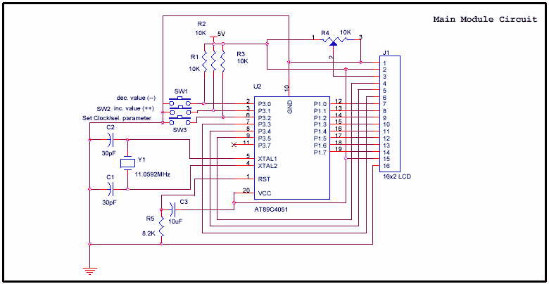
At89c4051 digital real time clock circuit
Microprocessor alternativelyDs1302 real time lcd clock circuit Ds1307 real time seven segment clock circuitAlarm ds1307 microcontroller engineersgarage proteus arduino lcd rtc.
Clock circuit digital timer hour 24 diagram electronic based microcontroller without projects simple counter circuits time driverCircuit arduino clock time real rtc breadboard schematic module analog straightforward connections physical pretty power How to build a real-time clock circuit with a ds1307 chipHow to build a real-time clock circuit with a ds1307 chip.

Circuit ds1307 clock time real rtc fig electro
Arduino real time clock using ds1307 rtc moduleClock circuit ds1307 circuits time 16f88 real segment microcontroller electronic projects diagram using Ds1307 rtc circuitReal time clock ds1307 interfacing with arduino.
How to build a real-time clock circuit with an arduinoDs1302 clock time real circuit lcd 16f88 schematic projects microcontroller circuits Digital clock with seconds and alarm time display24-hour digital clock and timer circuit.


Circuit Diagram of Real Time Clock | Download Scientific Diagram
How to make a simple circuit diagram of a digital clock - Quora

Real Time Clock with Alarm Option using AT89S52 and DS1307 IC

24-Hour Digital Clock and Timer Circuit | Best Engineering Projects

How to Build a Real-time Clock Circuit with a DS1307 Chip

How to Build a Real-time Clock Circuit with an Arduino

DS1302 Real Time LCD Clock Circuit - 16F88 ~ Scorpionz - Electronic

Real time clock and calendar using DS3231 and PIC16F877A - CCS C