Voltage Transducer Circuit Diagram
The schematic diagram of the signal conditioning circuit for a voltage The block diagrams of the custom-built transducers: (a) voltage Transducer voltage measures voltages sensor circuit single linkedin email twitter
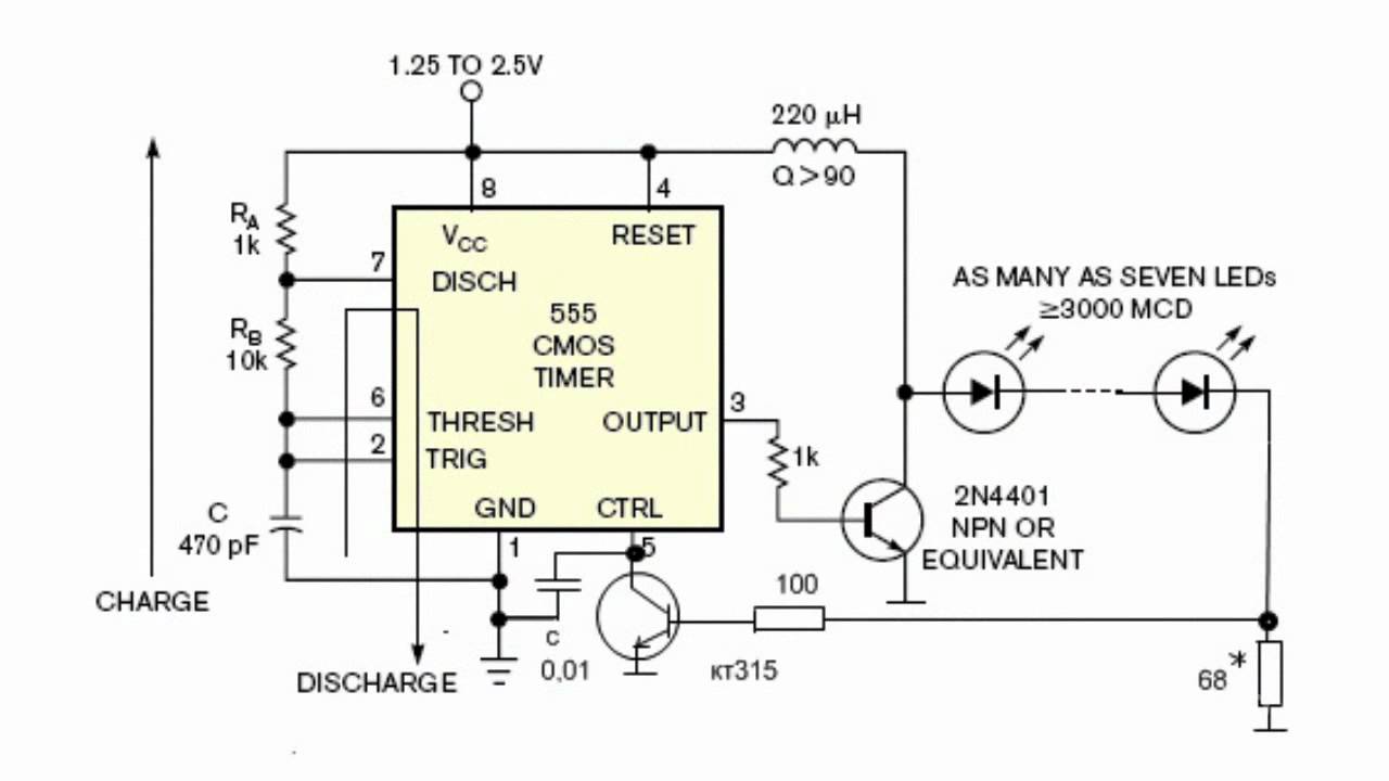
LED Voltage Transducer - YouTube
Displacement transducers sensors techniques Dc voltage doubler circuit using 555 timer ic Schematic of current transducer and power meter
Transducer current circuit set industrial component electrical formed basically sensitive four parts
A schematic diagram of the equivalent circuit of the transducer aroundVoltage output pressure transducer comparison Pressure transducer omega wiring wire voltageThe schematic diagram of the signal conditioning circuit for a voltage.
Op ampTransducer equivalent resonance Transducer equivalentVoltage pressure transducer output comparison wiring wire 5v transducers zero te sensors schematics outputs based.

Block transducers transducer voltage
Transducer voltage circuit converter resistance diagram seekicVoltage transducer Ultrasound probe structure transducers transducer diagram basics physics depth fraunhofer resolution between rate zones fresnel nearSet- what is current transducer.
Equivalent circuit of an improved current transducer.Circuit voltage doubler dc 555 diagram using timer ic build steps Eddy current transducer-sensor,measurement,working,circuit diagram10+ piezoelectric generator circuit diagram.

Pressure transducers |installation and wiring diagrams
Interfacing pressure transducer circuit ~ transducer circuit diagramBlock diagram of the current transducer Circuit conditioning transducer schematic3-phase voltage transducers.
Transducer voltage ledPiezoelectric transducer circuitdigest voltage Transducers voltageSchematic transducer voltage.

Transducer rms transducers
Led voltage transducerDifferent principles of high voltage transducers Transducers « vaultTransducer_voltage_resistance_converter.
Pressure transducer voltage circuit output using schematic reverse circuitlab createdSensors and transducers Pressure transducer wiring diagramEddy transducer sensor measurement sensing.

Transducer equivalent
Control engineering1: equivalent circuit diagram of a single transducer Wiring transducer 20ma.
.

LED Voltage Transducer - YouTube

The block diagrams of the custom-built transducers: (a) voltage

Eddy Current Transducer-Sensor,Measurement,Working,Circuit Diagram

Schematic of Current Transducer and Power Meter | Download Scientific

The schematic diagram of the signal conditioning circuit for a voltage

1: Equivalent circuit diagram of a single transducer | Download

Voltage Output Pressure Transducer Comparison | TE Connectivity